Digital inputs
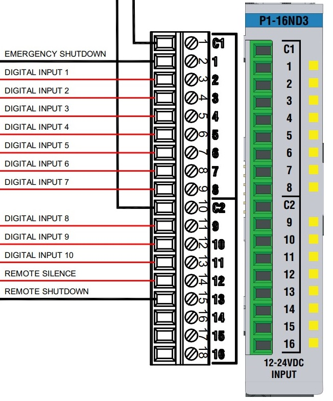
The digital input module (P1-16ND3) provides the connections for the digital sensor inputs. Digital inputs of sensors and switches are directly connected to the terminals of the digital PLC input module. The following information refers to the terminal designation (C1 to 16) of the modules (see figure above) and not to the designations on the terminals.
The terminals with red lines indicate the connections available for customer digital inputs. The black lines are part of the system wiring and may not be removed or added. Digital input 12 is optionally available for remotely switching off the horn. This means that 10 individual digital inputs are available which can be configured as normally open contacts or normally closed contacts. The configuration and use of the digital inputs is described in the corresponding instruction manuals.
All sensors must be connected with a two-wire cable. This cable (max. diameter 6 mm) is passed through one of the cable glands on the base of the unit and connected according to the electrical connection diagrams. The polarity of the sensors must be checked before connection. A short circuit when connecting a sensor results in one of the 24V control fuses being tripped.
One wire on the digital input is connected to a free terminal (2 to 11) on the PLC input module. The other wire is connected to one of the free inputs of the common 24V connection.
The cover of the input module (P1-16ND3) can be unfolded for access to the terminals on the connection. The screw version terminals require a 0.4 x 2.5 mm flat screwdriver to clamp the wires. The wire end is stripped to a length of 9 to 10 mm and inserted into the connecting terminal. The maximum permissible diameter of the stripped wires is 1.5 mm².
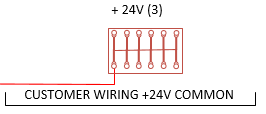
The 24V connection for digital inputs is as shown below.